Search News
Industry Portal
Popular Tags
Which Valve Specifications Help Prevent Chemical Media Leakage?

Author
Time
Click Count
A valve specification that prevents chemical media leakage is not a single line item. The effective specification matches the sealing arrangement, body and trim materials, pressure-temperature rating, stem or shaft design, and fugitive-emissions requirement to the actual chemical, including its concentration, temperature, vapor pressure, impurities, and operating cycle. A valve described only as “chemical resistant” or “zero leakage” leaves too much room for unsafe assumptions.
For many process duties, the first specification to examine is the pressure boundary: body, bonnet, end connections, gaskets, and fasteners must retain containment at the maximum expected pressure and temperature, including credible upset conditions. Leakage frequently begins at interfaces rather than through the main valve body. A suitable seat material will not compensate for a flange gasket attacked by the medium, a bolting set that loses preload during thermal cycling, or a body material that suffers localized corrosion.
Start with the leakage path, not the valve name
Ball, globe, diaphragm, gate, butterfly, plug, and needle valves each have different leakage paths. Selecting by valve type alone can produce an apparently suitable design with the wrong containment features. The specification should separate three concerns: external leakage to atmosphere, internal leakage across the closure element, and leakage through connected piping joints.
External leakage is commonly associated with stem packing, bonnet gaskets, body joints, actuator penetrations, and flange connections. This is the principal concern for toxic, volatile, corrosive, flammable, or environmentally regulated chemical media. Internal leakage occurs when fluid passes from the upstream side to the downstream side while the valve is closed. It can contaminate a downstream process, defeat isolation, or allow hazardous pressure to reach equipment that was assumed to be isolated.
A specification for hazardous chemical service should state which leakage condition matters. “Bubble-tight” is often used casually, yet its meaning depends on the test method, test medium, pressure, seat construction, and allowable leakage class. A resilient seat may provide very low shutoff leakage under a defined test, while its polymer compound may be unsuitable for the actual chemical temperature or pressure. A metal seat may tolerate heat and abrasion better but have a different permitted leakage level.
Sealing construction determines the primary containment level
Where atmospheric release is unacceptable, the sealing design deserves greater attention than the nominal valve style. A conventional packed stem can perform well when the packing set, stem finish, gland load, and cycle duty are compatible. It remains a dynamic seal, however, and its performance changes with wear, thermal movement, pressure variation, and adjustment.
For more demanding services, a bellows-sealed valve creates a welded metallic barrier around the moving stem. The packing, when provided, acts as a secondary seal rather than the first containment barrier. Bellows construction is especially relevant where a small stem emission cannot be tolerated, but the bellows material, cycle life, stroke, pressure differential, and corrosion resistance must be specified. A bellows that is chemically compatible in static exposure can still fail early if repeated cycling, vibration, or pressure pulsation exceeds its design duty.
Diaphragm valves isolate the operating mechanism from the medium with an elastomeric or polymer-lined diaphragm. Their body and lining options make them useful for corrosive fluids, slurries, and high-purity systems. The diaphragm is also a wear item. Its allowable temperature, pressure, flexing frequency, and resistance to permeation should be assessed together. Permeation is distinct from a visible leak: certain small molecules can migrate through some polymers without an obvious rupture or failed joint.
For quarter-turn valves, the stem seal and the relationship between seat design and pressure direction require close review. A cavity in a ball valve can trap liquid. If that trapped liquid expands when heated, pressure can rise inside the cavity even when the valve is shut. A cavity-relief feature, pressure-relieving seat arrangement, or an operating procedure that prevents trapped liquid exposure may be necessary. This issue is easy to overlook when a valve is specified only by line pressure.

Fugitive-emissions qualification should be explicit
Fugitive emissions are small, unintended releases from valve stems, shafts, body joints, and other external sealing locations. A request for a “low-emission valve” should identify the applicable test standard, temperature range, number of mechanical cycles, pressure, test fluid, and acceptance criterion. Without these details, two valves carrying similar marketing language may have been tested under very different conditions.
Common reference frameworks include ISO fugitive-emissions testing for industrial valves and applicable API or ASME requirements used for valve design, pressure ratings, and emissions-related service. The relevant document should be cited only when its scope matches the valve category and installation. A qualification for a manual valve does not automatically establish equivalent performance for an actuated valve that cycles frequently or applies side load to the stem.
Packing architecture affects emissions behavior. Multi-ring packing sets may combine graphite, PTFE-based materials, anti-extrusion rings, live-loading elements, and corrosion-resistant gland hardware. Live loading uses springs to maintain a more stable compressive force as packing relaxes, temperatures change, or the stem cycles. It is valuable only when the packing materials and spring components remain suitable for the chemical environment and operating temperature.
Stem surface condition also matters. Scratches, pitting, corrosion deposits, or excessive runout can create a path through otherwise appropriate packing. Specifications should define the required stem material and finish when the service is severe. The installed actuator, coupler alignment, and support arrangement must not impose bending loads that wear one side of the packing set.
Material compatibility must include the entire wetted assembly
Listing a corrosion-resistant body alloy is not enough. The wetted path can include the body, bonnet or cover, closure element, seat, stem, diaphragm, liner, body gasket, packing components, fasteners exposed to the medium, and coating or overlay systems. A chemically resistant body paired with an incompatible soft seat still has a direct failure path.
Compatibility must consider the actual medium rather than its broad chemical family. Acid concentration, dissolved salts, oxidizing potential, water content, chloride contamination, cleaning chemicals, and temperature can change material behavior sharply. Stainless steel that is acceptable for a dry or dilute stream may be vulnerable to chloride-driven localized corrosion in a hot aqueous service. A fluoropolymer may resist a chemical well but have insufficient mechanical stability at elevated temperature, under vacuum, or during rapid temperature changes.
Material selection also needs to account for the process sequence. A valve can be compatible with the production chemical yet fail during steam-out, solvent flushing, passivation, cleaning, or decontamination. If a line alternates between incompatible media, the specification should identify the full exposure envelope rather than the nominal process fluid alone.
Pressure and temperature limits require realistic operating margins
Pressure class and nominal pressure designation describe an important design boundary, but neither should be read as an unconditional operating permission. The allowable pressure changes with temperature and material group. A valve can meet the pressure requirement at ambient conditions while being unsuitable at the highest operating temperature. Conversely, vacuum service can collapse unsupported liners, draw air through imperfect seals, or change the behavior of packing designed mainly for positive pressure.
Thermal cycling deserves a separate note in the specification. Metal bodies, polymer seats, PTFE gaskets, graphite packing, and actuator components expand at different rates. Repeated heating and cooling can reduce bolt preload, relax packing, or create clearance changes at seals. A steady-state pressure-temperature rating does not describe this behavior by itself.
Pressure transients are another common blind spot. Fast-closing actuators, pump trips, flashing liquids, and blocked-in thermal expansion can produce short events that exceed normal line conditions. The valve body may survive the event while a seat, stem seal, diaphragm, or cavity seal loses integrity. Where such events are credible, the specification should identify the transient source and require a design review of the affected components.
End connections and assembly details are part of valve containment
Leakage prevention extends beyond the valve’s internal construction. Flanged connections require compatible facing type, gasket geometry, gasket material, bolt material, torque procedure, and flange alignment. Over-tightening can crush a soft gasket or distort a polymer-lined flange; under-tightening can allow relaxation and leakage after a temperature change. A mismatched flange face can damage the gasket before the system is pressurized.
Welded ends remove a bolted joint but introduce different controls. Heat from field welding can damage soft seats, liners, packing, coatings, or internal elastomers if the valve is not designed for that installation method. The purchase specification should state whether the valve will be welded in place, whether disassembly is required, and what heat-protection instructions apply. Post-weld cleaning is equally important when contamination could attack a high-alloy material or compromise high-purity service.
Threaded connections create many potential helical leak paths and are often less suitable for hazardous chemical service than welded or properly assembled flanged joints. When threads are used, the sealant must be compatible with the chemical and the expected temperature. Sealant fragments can also interfere with small passages, seats, or downstream instruments.
Internal shutoff specifications must reflect the isolation duty
Seat leakage class is important when the valve is used for process isolation, transfer segregation, reactor feed control, or maintenance isolation. The required class should be connected to the consequence of downstream leakage. For example, a valve used only for coarse flow control has different shutoff needs from one that separates reactive chemicals or protects a depressurized maintenance boundary.
Soft-seated valves commonly provide tighter shutoff at moderate conditions, but seat selection must address chemical attack, cold flow, abrasive solids, and pressure differential. Metal-seated valves may be better suited to elevated temperature, particulates, or severe cycling, although their specified shutoff leakage must be accepted for the service. A double-isolation arrangement does not automatically solve the problem if both valves share the same unsuitable material or if the space between them cannot be safely vented, drained, or monitored.
For valves intended to isolate a hazardous line for maintenance, consider whether a bleed or vent connection is required between isolation barriers. The valve configuration must ensure that any released fluid can be directed to a suitable closed drain, recovery system, or controlled disposal point. Adding a vent without defining its routing merely moves the leakage hazard to another location.
Installation can defeat a sound specification
A correctly selected valve can leak after installation because of pipe strain, unsupported actuator weight, incorrect orientation, debris, or damage during handling. Misaligned piping transfers bending load into the body and end connections. On a packed stem valve, external pipe movement and actuator misalignment can also disturb the stem’s travel path. Heavy actuators often require independent support so their weight does not load the valve neck or mounting hardware.
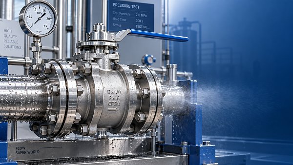
Before commissioning, pressure testing should distinguish between shell integrity, seat leakage, and external sealing performance. Test media must not create a compatibility problem of its own. Water testing can leave chlorides or moisture in systems intended for dry, reactive, or corrosion-sensitive service; pneumatic testing introduces stored-energy hazards and demands suitable controls. Test pressure, hold duration, inspection points, acceptance criteria, drying requirements, and restoration of protective caps or vents should be documented for the actual valve design.
Maintenance records should capture the observed leak location rather than simply recording “valve leak.” Stem leakage, body-joint leakage, flange leakage, seat passing, and diaphragm failure lead to different corrective actions. Repeated gland tightening may temporarily reduce a packing leak while accelerating stem wear or masking a material incompatibility. A leak that appears only after thermal cycling points toward a different investigation than one present at first pressurization.
Common specification questions
Is a bellows seal always necessary for chemical media?
No. It is selected when the consequence of stem emissions, chemical toxicity, volatility, or containment requirements justify a secondary metallic barrier. For compatible low-hazard duty, a qualified packed-stem arrangement may be suitable. Bellows selection still requires confirmation of cycle life, alloy resistance, and failure detection or secondary sealing provisions where required.
Does PTFE guarantee leak-free chemical service?
No. PTFE has broad chemical resistance, but sealing performance also depends on pressure, temperature, mechanical support, creep resistance, permeation behavior, and thermal cycling. A filled PTFE, reinforced seat, alternative fluoropolymer, graphite-based packing, or metallic seal may be more appropriate for a specific duty.
What information should be available before final valve selection?
The chemical composition and concentration, normal and upset pressure-temperature conditions, phase, solids content, operating frequency, required shutoff duty, external-emissions target, line connection details, cleaning media, and installation orientation form the minimum technical basis. Missing information should be treated as an unresolved design condition, not filled in with a generic chemical-service designation.
The strongest leakage-prevention specification connects each containment feature to a defined failure mode: chemical attack, packing emission, seat passing, gasket relaxation, trapped-fluid pressure, thermal movement, or installation stress. When those links are explicit, the valve selection can be reviewed against real process conditions instead of relying on a broad material label or a nominal pressure rating.
Recommended News
 Oct 16, 2026How Do I Size a Pump System for Variable Production Demand?How do I size a pump system for variable production demand? Discover how to match flow, head, VFDs, and staged pumps to reduce energy waste and keep production reliable.
 Sep 27, 2026How valve pressure containment data supports safe system designValve pressure containment data helps engineers verify ratings, materials, tests, and temperature limits for safer system design. Explore practical selection insights.
![]() Oct 16, 2026Which Valve Specifications Help Prevent Chemical Media Leakage?Which valve specification prevents chemical media leakage? Explore sealing, materials, pressure ratings, and fugitive-emission features for safer chemical containment.
 Sep 20, 2026When strategic procurement reduces total cost without disrupting supplyStrategic Procurement lowers total cost without risking supply continuity. Learn how to compare delivered value, qualify suppliers, and prevent hidden rework.
 Sep 04, 2026When do oil and gas industrial valves require API 6D certification?Industrial Valves for oil and gas may require API 6D certification for pipeline isolation and transportation systems. Learn key compliance triggers, procurement checks, and safety standards before sourcing.
 Aug 27, 2026Industrial supply chain analysis for finding single-source riskIndustrial Supply Chain Analysis resilience helps uncover hidden single-source risks, map critical dependencies, and build practical mitigation plans for stronger operational continuity.
 Jul 21, 2026How to Evaluate an ISO Compliance Equipment ManufacturerISO compliance equipment manufacturer evaluation starts with more than certificates. Learn how to verify capability, traceability, documentation, and supply reliability.
 Jul 12, 2026Rotary Lobe Pump Exporter Checklist: Certifications, Materials, and Service RiskRotary lobe pump exporter checklist: verify certifications, wetted materials, traceability, and after-sales support to reduce compliance risk, hidden costs, and downtime before you buy.
 Jul 10, 2026ASME Certified Components Quotation: Cost Drivers and Hidden Review PointsASME Certified Components quotation explained: uncover real cost drivers, hidden review points, and supplier risks to compare quotes fairly and avoid costly approval delays.
 Jul 09, 2026How to Compare Global Water and Oil Valve Tenders Databases by Coverage and Update SpeedGlobal water and oil valve tenders database comparison starts with coverage and update speed. Learn how to spot faster, deeper tender intelligence before opportunities are missed.
![]() Jul 07, 2026Air Filters for Clean Processes: When Pressure Drop Becomes a Cost ProblemAir filters can quietly raise clean-process costs through pressure drop, energy loss, and downtime. Learn how to balance filtration efficiency, uptime, and lifecycle savings.
![]() Jul 07, 2026Metering Pump Manufacturer Checklist for Accuracy and Lifecycle CostMetering pump manufacturer selection goes beyond flow accuracy. Learn how to compare lifecycle cost, reliability, materials, service support, and compliance before you buy.
![]() Jul 07, 2026CIP Rotary Lobe Pump Selection: Cleanability, Shear, and Downtime RiskCIP rotary lobe pump selection starts with cleanability, shear control, and downtime risk. Learn how to choose a hygienic, low-maintenance pump that protects product quality.
 Jul 06, 2026Food Grade Lobe Pump Shear: How It Affects Product TextureFood grade lobe pump shear directly affects texture, particle retention, and filling stability. Learn how to evaluate shear, protect product quality, and choose the right hygienic pump.
 Jun 30, 2026API Valve Tenders: Cost and Delivery Risks in Global ProjectsGlobal water and oil valve tenders for API valves often hide cost and delivery risks. Learn how to compare bids, spot exclusions, and avoid expensive project delays.
 Jun 27, 2026Slurry Pump for Mining: Common Wear Problems and FixesSlurry pump for mining wear issues explained: spot abrasive wear, cavitation, corrosion, seal leaks, and bearing damage early, with practical fixes to cut downtime and repair costs.
 Jun 25, 2026How to Use an Industrial Buyers Directory for Construction VendorsIndustrial buyers directory for construction: learn how to find, compare, and qualify vendors faster, reduce sourcing risk, and make smarter purchasing decisions for complex projects.
 Jun 23, 2026Radiators vs Heat Exchangers: Which Fits Industrial Cooling Better?Radiators or heat exchangers? Discover which industrial cooling solution delivers better efficiency, uptime, and cost control—and when radiators are the smarter choice.
 Jun 18, 2026Rotary Lobe Pump Factory Checklist: What to Verify Before OrderingRotary lobe pump factory checklist: verify application fit, quality control, material traceability, lead times, and support before ordering to reduce risk and buy with confidence.
 Jun 17, 2026How to Choose Dust Collectors for Fine Powder Controldustcollectors for fine powder control: learn how to compare collector types, filter media, safety, and lifecycle cost to choose a safer, more efficient system.
 Jun 15, 2026How to Compare Storage Solutions for Energy Density and RiskStorage solutions compared by energy density and risk: learn how to evaluate safety, compliance, lifecycle cost, and reliability to choose the right system with confidence.
 Jun 14, 2026Car Batteries Wholesale: Cost Factors, MOQ, and Warranty RisksCar batteries wholesale buying is about more than price. Learn key cost drivers, MOQ terms, landed cost, and warranty risks to choose safer suppliers and protect margins.
 Jun 11, 2026How to Evaluate an Air Compressors Supplier for UptimeAir compressors supplier selection directly affects uptime. Learn how to compare service, parts, data visibility, and technical fit to reduce risk and choose with confidence.
![]() Jun 09, 2026How to Read Centrifugal Pump Head and Flow Data CorrectlyLearn how to read centrifugal pump head and flow data correctly, avoid sizing mistakes, check BEP and NPSH, and make smarter pump selection decisions with confidence.