Search News
Industry Portal
Popular Tags
How grinding accuracy affects precision linear guide manufacturing
Author
Time
Click Count
How grinding accuracy affects precision linear guide manufacturing
Grinding accuracy determines more than dimensional conformity in precision guides manufacturing. It influences raceway geometry, surface texture, preload consistency, and the reliability of the assembled motion system. A rail can pass a basic dimensional check yet produce uneven running resistance or poor motion accuracy once its carriage is installed.
The practical challenge is separating errors created during grinding from those introduced by assembly, mounting, lubrication, or measurement. Tightening every tolerance is rarely the best answer. What matters is identifying which ground features control contact conditions, how those features are verified, and whether acceptance evidence represents the guide’s actual operating condition.
The critical relationship is between the raceway and its datum
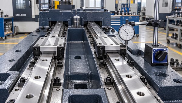
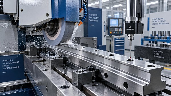
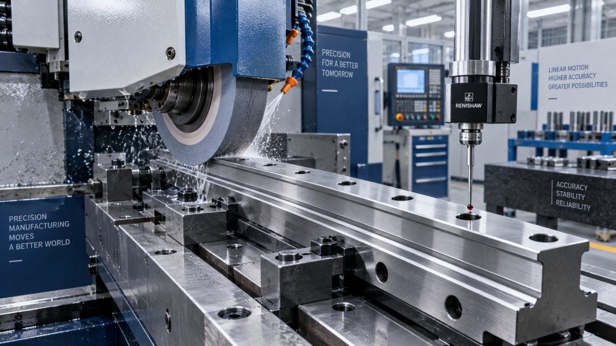
In a recirculating linear guide, balls or rollers transmit load through raceways in the rail and carriage. Grinding establishes the profiles and positions of these contact surfaces after hardening. It also finishes reference faces that locate the components during assembly and installation.
These features cannot be evaluated independently. A correctly shaped raceway positioned incorrectly relative to the mounting datum can change assembled height, lateral position, or load sharing. Conversely, a dimensionally consistent rail may still have local profile errors that alter contact stress.
For ball guides, groove curvature and the relationship between ball diameter and groove geometry influence contact behavior. For roller guides, raceway alignment and profile control are particularly relevant to avoiding concentrated loading near roller ends. The acceptable geometry depends on the manufacturer’s contact design; there is no universal raceway tolerance suitable for every guide family.
This is why a drawing that specifies only rail width, height, and overall straightness leaves an important gap. Inspection needs a defined datum structure and a way to evaluate the raceway relative to it. Otherwise, two suppliers can report similar dimensions while delivering different assembled behavior.
Preload makes small grinding errors harder to ignore
Preload removes internal clearance and increases stiffness by establishing an initial contact load. Depending on the guide design, manufacturers may achieve it through rolling-element selection, controlled raceway relationships, or other assembly methods.
The important distinction is between specified preload and consistent preload along the travel. Local variation in raceway spacing or profile can change contact conditions as the carriage moves. The result may be a tight region, fluctuating running resistance, or uneven internal loading even when the guide carries the correct preload designation.
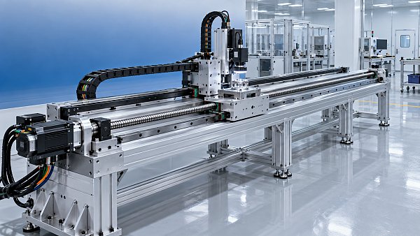
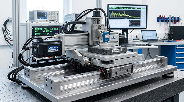
Consider a servo-driven inspection stage moving slowly through its measurement zone. Position feedback may let the controller compensate for some motion disturbances, but it does not remove fluctuating friction, heat generation, or contact stress. A guide that feels acceptable during a quick manual stroke can behave differently at low speed under load.
Increasing preload is not a reliable cure for poor grinding. It may improve stiffness while increasing friction and sensitivity to mounting errors. If a supplier proposes a higher preload class to address unstable motion, ask whether raceway geometry and installation alignment have been checked first.
A smoother surface is not automatically a better raceway
Surface roughness matters because rolling contact operates through a lubrication film whose behavior depends on speed, lubricant properties, temperature, and load. Surface peaks can interact when film separation is insufficient. However, a low roughness value alone does not establish satisfactory contact performance.
Roughness, waviness, and form describe different aspects of the surface. A raceway may have a favorable Ra value while retaining periodic waviness from machine vibration or wheel-related effects. Such features can contribute to force ripple or vibration, depending on their wavelength and the contact configuration.
Measurement settings therefore belong in the acceptance requirement. The instrument, filtering, evaluation length, measurement direction, and access to the groove all affect the result. Comparing roughness numbers without these details can create a false impression of agreement.
There is also a metallurgical concern that a surface trace cannot resolve. Excessive grinding heat can cause tempering damage, rehardening, or unfavorable residual stresses in hardened steel. Depending on the damage mechanism, cracking may occur. A visually bright finish does not rule out thermal damage.
Where this risk is significant, inspection may include qualified etching, magnetic Barkhausen noise testing, or other validated methods appropriate to the material and defect. These methods are not interchangeable. Their sensitivity and acceptance criteria need to be established for the component, rather than borrowed from an unrelated part.
What process evidence is worth reviewing?
Wheel specification, dressing practice, stock removal, coolant delivery, and workholding all influence the finished result. Asking only for the grinding machine’s nominal positioning accuracy misses most of this chain.
A more useful supplier discussion examines how wheel wear is detected, when dressing occurs, how coolant conditions are controlled, and how the rail is supported without distortion. Long rails deserve particular attention: clamping can temporarily straighten a component, only for it to recover a different shape when released. Inspection should distinguish free-state geometry from geometry under specified support or mounting conditions.
Inspection must connect component geometry to assembled motion
No single inspection method establishes linear guide quality. Component measurements explain whether the ground features conform; assembled tests show how those features interact with rolling elements, seals, lubrication, and carriage construction.
Temperature deserves explicit control when dimensional tolerances are tight. The rail, fixture, and measuring equipment must reach a suitable thermal condition, and the measurement report should record relevant conditions. Resolution is not the same as measurement uncertainty; displaying more decimal places does not make a borderline result trustworthy.
For production acceptance, sampling should also reflect the process. Results taken only immediately after wheel dressing may not represent parts produced later in the dressing interval. Capability evidence is more informative when it covers normal tool wear, setup changes, and relevant rail lengths.
Use standards to define the measurement, not to replace the specification
ISO 1101 provides a framework for geometrical tolerancing, while the ISO 21920 series addresses profile surface texture. These references help make drawing requirements and inspection reports unambiguous. They do not supply a universal grinding tolerance for precision linear guides.
ISO 14728-1 addresses dynamic load ratings and rating life for linear motion rolling bearings; ISO 14728-2 addresses static load ratings. These are relevant to bearing selection and engineering assessment, but a catalog load rating is not evidence that an individual raceway is free of grinding damage or geometric defects.
Where conformity decisions involve results close to a tolerance boundary, ISO 14253-1 provides decision rules that account for measurement uncertainty. The applicable edition, contractual requirements, and any agreed decision rule should be confirmed before acceptance disputes arise.
Accuracy-class names also need care. Manufacturer classifications are not automatically interchangeable. Compare their actual definitions, including running parallelism, dimensional variation, reference surfaces, and measurement conditions, rather than relying on the class label.
Keep manufacturing defects separate from installation risk
A ground rail is not the complete axis. Mounting-surface flatness, parallelism between rails, bolt-tightening sequence, contamination, and structural deformation can change its behavior after installation. A guide that binds on the machine but runs correctly on a verified reference fixture needs an installation investigation before the grinding process is blamed.
This distinction matters for safety. Guide deterioration can affect motion stability and mechanical integrity, but grinding acceptance alone cannot establish machine safety. Vertical axes, suspended loads, and hazardous motion require application-specific protective measures; guide preload is not a load-holding safeguard.
For technical benchmarking repositories such as Global Core Systems & Advanced Technology (G-CST), the useful comparison is the connection between specifications, test conditions, and traceable evidence. A headline accuracy class without its measurement basis contributes little to a reliable cross-supplier assessment.
Before approving a guide, agree on the critical raceway characteristics, the assembled-motion test, and the conformity decision rule. If resistance varies along travel, retain the force trace and correlate it with rail position and geometry measurements. That evidence gives the manufacturer something actionable—and helps prevent an installation problem, lubrication issue, or grinding defect from being accepted under the wrong explanation.
Recommended News
 Oct 19, 2026How Do I Validate Replacement Linear Guides for an Existing Machine?How do I validate replacement parts for an existing machine? Discover essential linear guide checks for fit, load capacity, accuracy, and safe commissioning before approving a replacement.
 Oct 20, 2026How grinding accuracy affects precision linear guide manufacturingIn precision guides manufacturing, grinding accuracy drives raceway quality and preload consistency. Discover key inspection checks for smoother motion and reliable performance.
 Sep 19, 2026When does a longer travel range raise linear motion stage wholesale costs?Linear motion stage travel range wholesale costs rise when longer strokes demand stronger structures, upgraded drives, precision feedback, and shipping support. Compare smarter before you buy.
 Jul 12, 2026How to Compare Miniature Motion Systems Suppliers for Precision and Lead TimeMiniature motion systems suppliers should be compared on precision, lead time, compliance, and lifecycle support. Learn how to shortlist reliable partners and reduce sourcing risk.
 Jul 04, 2026Linear Guide Rail for CNC: How to Choose Load, Accuracy, and Service LifeLinear guide rail for CNC selection made simple: learn how to balance load, accuracy, preload, sealing, and service life to cut downtime and choose the right rail with confidence.
 Jun 30, 2026Cross Roller Bearing Supplier Checklist for Stable PrecisionCross roller bearing supplier checklist for buyers who need stable precision. Learn how to verify quality, traceability, engineering support, and delivery reliability before you commit.
 Jun 19, 2026Linear Guide Rail Supplier Checklist for Load Accuracy and Service LifeLinear guide rail supplier checklist for better load accuracy and longer service life. Compare quality control, preload, lubrication, and support before you buy.
 Jun 16, 2026Telescopic Rail OEM Checklist: Load, Tolerance, and Lead TimeTelescopic rail OEM checklist covering load, tolerance, finish, and lead time. Learn how to compare suppliers, reduce sourcing risk, and choose rails that perform reliably at scale.
 Jun 06, 2026How to Choose a Measuring Tape for Accurate Site WorkMeasuringtape selection affects accuracy, speed, and rework on site. Learn the key features, common mistakes, and how to choose the right tape for reliable results.
![]() Jun 04, 2026Linear Guide Frictional Resistance: When Maintenance Solves DriftLinear guide frictional resistance causes drift, positioning errors, and unstable motion. Learn how targeted maintenance restores accuracy, cuts downtime, and prevents repeat service issues.
![]() Jun 04, 2026How Linear Guide Frictional Resistance Affects Positioning StabilityLinear guide frictional resistance directly impacts positioning stability, repeatability, and servo response. Learn how preload, lubrication, and mounting affect precision performance.
 May 23, 2026Next-Gen Linear Motor Technology for Faster PositioningNext-gen linear motor technology drives faster positioning, smoother motion, and higher repeatability. Discover where it delivers the biggest gains in automation performance.
 May 22, 2026Linear Motion Market Growth Report: Where Demand Is ShiftingLinear motion market growth report: discover where demand is shifting across automation, semiconductors, precision manufacturing, and infrastructure to identify high-fit growth opportunities.
 May 22, 2026Linear Rail Parallelism Standards That Prevent BindingLinear rail parallelism standards explained with a practical checklist to prevent binding, cut wear, improve accuracy, and keep motion systems running smoothly.
 May 21, 2026Stiffness and Damping in Guides: Selection MistakesStiffness and damping in guides directly affect accuracy, vibration control, and lifecycle cost. Learn the most common selection mistakes and make smarter, lower-risk purchasing decisions.
 May 20, 2026Linear Guide Frictional Resistance and Its Impact on MotionLinear guide frictional resistance directly affects motion accuracy, wear, and uptime. Learn key causes, maintenance checks, and practical ways to reduce friction issues fast.
 May 20, 2026Ball Screw Lead Precision Data: Tolerance vs PositioningBall screw lead precision data explained: learn how tolerance differs from real positioning accuracy, avoid costly spec mistakes, and choose motion systems with more confidence.
 May 20, 2026Linear Module Factory Selection for Fast Project DeliveryLinear module factory selection affects project speed, quality, and risk. Discover how to compare lead time, engineering support, and precision capability for faster delivery.
 May 19, 2026Telescopic Rail OEM Options for Cleanroom Tool AccessTelescopic rail OEM solutions for cleanroom tool access: compare materials, load stability, customization, and compliance factors to reduce downtime and choose the right supplier.
 May 19, 2026Linear Motion Stage Wholesale: Accuracy Costs ExplainedLinear motion stage wholesale costs explained: see how accuracy grades, materials, load stability, and supplier validation shape pricing, risk, and long-term ROI.
 May 18, 2026How to Evaluate a Linear Guide Rail Supplier for Cleanroom Motion SystemsLinear guide rail supplier selection for cleanroom motion systems starts with contamination control, lubrication, traceability, and quality data. Learn how to compare suppliers and avoid costly risks.
 May 03, 2026How to Evaluate a Precision Manufacturing Supplier for Stable QualityPrecision Manufacturing supplier evaluation starts with scenario fit. Learn how to assess quality stability, traceability, compliance, and supply resilience for smarter sourcing.
 Apr 21, 2026Precision Motion Control Problems That Look Like VibrationPrecision Motion Control issues often mimic vibration in Semiconductor Fabrication Equipment. Learn how Industrial Software Solutions, High-performance Bearings, and Technical Benchmarking reduce downtime and risk.
 Apr 21, 2026Why Precision Manufacturing Still Misses Tight TolerancesPrecision Manufacturing still misses tight tolerances—learn how Digital Twin Technology, Reliability Engineering, Strategic Procurement, and Material Innovation improve repeatability and supplier confidence.